

Views: 137 Author: Site Editor Publish Time: 2026-10-02 Origin: Site


Unplanned downtime, shaft fatigue, and premature bearing wear are direct consequences of a poor setup. For heavy-duty and marine applications, imprecise installation compromises the entire propulsion or drive train. You simply cannot afford arbitrary positioning when thousands of horsepower transfer through your driveline. A minor installation error cascades quickly into severe mechanical stress.
This intermediate bearing setup guide provides a robust technical framework for evaluating modern alignment strategies. It helps you validate load distribution accurately and decide when to rely on in-house maintenance versus specialized engineering services. We will explore the vital nuances of offset calculations and dynamic load shifting.
Readers will learn how to assess setup methodologies against strict industry standards. You will uncover proven ways to mitigate operational risks and ensure long-term structural integrity. Ultimately, we equip you with the practical knowledge necessary to maintain peak performance and avoid catastrophic equipment failure.
Correct setup relies on intentional offset rather than perfect straight-line alignment to account for dynamic operating conditions.
Load distribution must be validated using empirical methods (e.g., jack-up tests) to ensure compliance with operational tolerances.
Selecting the right alignment method depends on the system's operational state (cold vs. hot, drydock vs. afloat).
Partnering with certified alignment specialists mitigates compliance risks and ensures class society standards are met.
A marine shaft system rarely operates in a purely rigid state. Heavy industrial drive trains share this highly dynamic nature. Hull deflections occur continuously during normal operation. Thermal growth alters metal dimensions predictably. Hydrodynamic forces shift shaft dynamics constantly. You cannot treat these massive rotating assemblies as static rigid bodies.
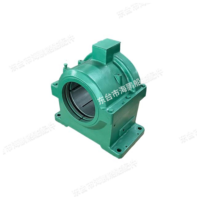
The intermediate bearing serves a highly critical function within this dynamic environment. It supports the immense dead weight of the forged steel shaft. It actively controls bending stresses along the unsupported span. Furthermore, it prevents harmful vibration transfer from reaching the main engine. It also shields the delicate reduction gearbox components from excessive radial forces. Without precise structural support, the heavy shaft sags naturally. This unsupported sag creates severe bending moments leading to metal fatigue.
Improper installation carries heavy, unavoidable consequences. You risk wiping the white metal babbitt lining entirely. Damaged stern tube seals lead to immediate fluid leaks and environmental hazards. In worst-case operational scenarios, you face catastrophic shaft shear. A sheared driveline leaves a vessel completely dead in the water. Industrial plants face total production halts. Precision matters deeply for maintaining structural system integrity over decades of operation.
Engineers evaluate two primary approaches for setting up complex drivelines. Traditional straight-line alignment assumes a perfectly straight rotational axis. You align all supporting pedestals to a single optical or laser line. This traditional method works exceptionally well for short, highly rigid assemblies. However, it often fails drastically for long, flexible propulsion shafts.
Rational alignment offers a technically superior alternative. We also call this curved shaft alignment. It pre-calculates the natural sagging behavior of the rotating equipment. Gravity exerts a constant downward pull on heavy steel spans. This creates a natural catenary curve. Rational methodology embraces this natural bending shape. It intentionally positions the pedestals to support the inherent catenary curve rather than fighting it.
Installing a bearing perfectly on-center is often a critical setup error. Dynamic operating conditions demand intentional spatial offsets. Calculated vertical offsets accommodate the natural bending line of the steel. Horizontal offsets counteract intense torque reactions generated under full load. Proper offsets optimize the critical gear mesh footprint. They also protect the main engine crankshaft from severe overloading.
Application realities heavily dictate component choices and setup parameters. You must seriously consider axial thermal expansion. Engines and gearboxes grow dimensionally as they reach operating temperatures. The heavy driveline expands longitudinally. A sliding intermediate bearing accommodates this specific axial movement flawlessly. It allows the heavy steel to expand freely while maintaining strict radial support. Setup calculations must factor in this sliding movement accurately. If you lock the pedestal axially, thermal growth will ultimately destroy the thrust collar.
Alignment Strategy Comparison Matrix
Feature | Straight-Line Methodology | Rational (Curved) Methodology |
|---|---|---|
Core Assumption | Assumes driveline remains perfectly rigid. | Calculates natural gravity-induced sag. |
Ideal Application | Short spans, rigid industrial pumps. | Long spans, marine propulsion trains. |
Offset Utilization | Zero offset target. | Intentional vertical/horizontal offsets. |
Dynamic Reliability | Poor under heavy thermal growth. | Excellent handling of operational shifts. |
Theoretical software models always look perfect on a computer screen. Practical load verification proves these models in the physical field. You must actively transition from theoretical calculations to physical reality. Actual physical reactions rarely match theoretical predictions perfectly. Unseen hull deformations change the baseline parameters entirely.
Field engineers use specific evaluation tools to verify actual operating loads.
Jack-up tests: This represents the industry standard for measuring actual reactions. Technicians place a specialized hydraulic jack directly next to the pedestal. They lift the steel mass slightly. A calibrated load cell records the exact lifting force. Dial indicators measure the microscopic lift distance. This procedure plots a hysteresis loop graph. The exact center of this loop reveals the true applied load.
Strain gauge alignment: This advanced method evaluates bending moments directly from the rotating surface. Technicians bond highly sensitive strain gauges to the steel. They rotate the equipment slowly. The gauges measure microscopic surface strains. Specialized software converts these minute strains into exact bending moments. This offers vastly higher accuracy for complex installations.
We must strictly benchmark these test results against established tolerances. Original equipment manufacturers provide essential baseline specifications. Authoritative class societies strictly enforce these technical rules. Organizations like ABS and DNV dictate allowable load variations. Typically, actual measured loads must fall within +/- 20% of the theoretical calculated values to pass inspection.
Dynamic load changes severely complicate these baseline tolerances. A large ship changes draft between fully loaded and ballast conditions. Deep heavy drafts bend the hull structure upward. Light drafts let the hull sag downward naturally. You must factor these varying operational drafts into acceptable baseline tolerances. An intermediate shaft bearing might show perfect load distribution in drydock. It could become completely unloaded once afloat. Trustworthy validation requires comprehensive testing in the vessel's normal operating condition.
Selecting the correct methodology requires carefully evaluating your specific project constraints. Modern tooling provides truly incredible precision. Laser measurement systems measure spatial distances down to the micron. Optical alignment transits offer excellent long-range visual accuracy. However, traditional analog methods remain highly relevant in specific scenarios. Piano wire and mechanical dial indicators are exceptionally reliable. They require no batteries, no software updates, and handle harsh environments well.
You should always choose tools based on project scale and complexity. Budget constraints also naturally drive your final tool selection.
Environmental variables introduce severe risks during practical implementation. You must mitigate these external factors carefully to ensure data integrity:
Sunlight distortion: Sunlight intensely heating one side of a steel hull causes massive thermal bowing. Always take critical final readings at night or early morning to avoid solar deflection.
Ambient temperature shifts: Large atmospheric temperature swings alter the calibration of sensitive laser targets.
Drydock vs afloat conditions: Drydock wooden blocks push up unevenly on the bottom structure. Afloat conditions provide completely uniform hydrostatic pressure. Final load verification must always occur afloat.
Fluid temperatures: Cold lubricating oil affects running clearances much differently than hot operational oil.
Data integrity forms the absolute foundation of any successful project. Transparent assumptions prevent catastrophic downstream errors. Engineering calculations are only as good as the raw input data. You must measure physical dimensions precisely. Material density variations change fundamental weight calculations. You need highly precise pedestal locations along the entire span. Guesswork in any of these variables renders the entire software model completely useless. Always double-check older shipyard drawings against modern physical measurements.
Deciding exactly who executes the setup requires a blunt capability assessment. You need a clear, objective decision framework. Does your internal maintenance team possess specialized modeling software? Do they have recent, proven experience handling complex drivelines? Routine inspection often fits easily within in-house capabilities. However, a full realignment usually requires hiring a specialized technical service.
Evaluate potential third-party contractors carefully across several crucial dimensions.
Tooling expertise matters immensely during execution. Do they utilize advanced 3D finite element modeling? Can they deploy continuous real-time laser measurement systems? You want a technical partner using state-of-the-art diagnostic equipment.
Compliance awareness is equally critical for marine applications. Commercial operations require strict class society approval. Are the bidding contractors highly familiar with ABS or DNV reporting standards? An uncertified load test report holds absolutely no value during a port state inspection.
Assess their analytical diagnostic capability thoroughly. Can they perform deep root-cause analysis on existing failures? You do not just want technicians to execute standard setups blindly. You need experienced engineers who correctly diagnose why the previous component wiped. They should easily identify underlying hull flexibility issues or abnormal vibration signatures.
Take clear next-step actions before issuing a Request for Quotation (RFQ). Gather all relevant technical documentation first. Compile original installation drawings. Collect previous alignment records and historical load test reports. Prepare a detailed, transparent operational history. Giving external engineers accurate historical data ensures a faster, highly accurate technical quotation.
Successful setup is an exercise in mastering dynamic forces. It requires highly precise offset calculations and rigorous load validation. You cannot rely on static, straight-line assumptions anymore. Real-world machinery bends, heats, and shifts continuously during operation.
We strongly advise moving away from reactive, emergency alignment fixes. You should adopt proactive, predictive modeled alignment strategies. Proper modeling catches potential overload conditions long before they destroy expensive hardware. This approach significantly extends the operational lifespan of your entire driveline.
We encourage you to audit your current historical records immediately. Consult your internal engineering teams to assess current asset health. If you lack recent jack-up test data, take decisive action now. Contact certified alignment specialists to review your specific engineering models. Protect your mechanical assets properly through verified precision.
A: Standard tolerances vary based on specific manufacturer guidelines and class society rules like ABS or DNV. Generally, operational standards allow a +/- 20% deviation from the theoretically calculated baseline load. Technicians must verify this deviation empirically using jack-up tests. Dynamic factors, such as varying vessel drafts and cargo conditions, heavily influence the acceptable final tolerance range.
A: Overheating usually stems from ignored implementation realities. It is likely caused by an incorrect spatial offset calculation or a failure to account for axial thermal expansion. If the bearing housing cannot slide freely, thermal growth applies massive axial force against the thrust collar. Unpredicted hull deflections post-setup can also drastically increase radial loads, generating excessive frictional heat.
A: Engineers determine the correct offset through rational alignment calculations. They utilize specialized finite element analysis software. This software meticulously models shaft stiffness, component weight, bearing span distances, and hydrodynamic forces. The goal is to establish an intentional catenary curve that ensures equalized radial load distribution across all support points at normal operating temperatures.


