

Views: 0 Author: Site Editor Publish Time: 2026-10-21 Origin: Site


Discovering water pouring in at the top of the propeller shaft right after a vessel refit triggers immediate panic. You just spent heavy capital on dry-docking. Now you have a flooding bilge or an active oil leak. This points to a severe failure. You need to fix it fast. Diagnosing the exact mechanism behind the failure means separating normal mechanical break-in behaviors from severe installation errors. Traditional packing glands behave differently post-launch compared to modern dripless mechanical face seals. Resolving post-installation leaks demands a systematic diagnostic approach. We must differentiate between human error during assembly, environmental mismatches, and actual component defects. Isolating the root cause lets you determine if you need minor in-water adjustments, specialized support, or an immediate return to the shipyard. We will break down exactly how to stop the water and secure the vessel.
Immediate Diagnostics: Most post-installation leaks stem from improper bellows compression, shaft surface scoring, or face contamination rather than manufacturing defects.
Thermal vs. Hydrodynamic Failures: Over-tightening causes rapid thermal degradation, while inadequate pressure control leads to hydrodynamic imbalance and flooding.
Environmental Matching: Operating in abrasive waters without an anti sand stern shaft seal accelerates face wear, causing premature failure even in newly installed units.
System-Specific Risks: Water-lubricated systems risk catastrophic bilge flooding, while oil-lubricated systems face environmental fines from oil leakage and severe bearing damage.
Vendor Accountability: Long-term reliability depends heavily on strict marine sealing equipment quality control and utilizing OEM-verified replacement stern shaft seal parts.
Establishing operational tolerances is the first step in diagnosing any marine sealing issue. Different sealing technologies operate on entirely different mechanical principles. The definition of a leak varies depending on the hardware installed. Traditional stuffing boxes rely on a controlled amount of water ingress to lubricate and cool the flax packing material. Modern dripless mechanical face seals and elastomeric lip seals are engineered for absolute fluid containment. Understanding these baseline success criteria prevents crews from making unnecessary adjustments that damage a properly functioning system.
During the initial break-in period, a newly repacked traditional stuffing box naturally exhibits a higher drip rate. You must allow the packing to seat itself under light compression before making final adjustments. A rate of eight to ten drops per minute while the shaft is rotating is standard. The gland temperature must remain cool to the touch. When the shaft is stationary, the dripping should nearly stop. Attempting to eliminate this drip entirely by over-tightening the gland nuts will instantly burn the packing material and score the propeller shaft.
Modern dripless mechanical seals operate under a strict zero-tolerance baseline. These systems utilize highly polished carbon graphite stators mating against stainless steel or silicon carbide rotors. If a dripless seal allows water into the bilge, the hydrodynamic film between the mating faces has failed. In commercial oil-lubricated stern tubes, the stakes are higher. Zero-tolerance oil leakage is mandatory. Any visible oil sheen in the water or a dropping level in the gravity header tank indicates a severe breach in the outboard lip seals. You must intervene immediately to prevent environmental fines and bearing failure.
To establish a proper baseline after a refit, follow these verification steps:
Identify the exact seal type and manufacturer specifications installed during the refit.
Measure the baseline drip rate over a strict 60-second interval while the shaft rotates at idle speed.
Record the ambient raw water temperature and compare it against the external seal housing temperature using an infrared thermometer.
Inspect the immediate bilge area for any signs of oil emulsion or excessive salt accumulation.
Ignoring excessive stern shaft seal leakage initiates a compounding cycle of mechanical degradation. In water-lubricated systems, continuous high-volume ingress overwhelms bilge pumps. This leads to localized flooding that damages adjacent electrical systems and auxiliary machinery. Persistent leakage often masks the physical destruction of the shaft itself. As packing materials crystallize from excessive heat, they act like a grinding wheel against the rotating shaft. This creates deep grooves that eventually require the shaft to be removed and machined or entirely replaced.
For oil-lubricated configurations, early warning signs include emulsified oil in the header tank. This indicates water bypassing the outboard seals. Salt water displaces the lubricating oil and destroys the white metal babbitt bearings. The friction generated by compromised lubrication can weld the bearing to the shaft. This results in a catastrophic propulsion failure at sea. Early detection and immediate corrective action keep the vessel safe and operational.
Seal Technology | Acceptable Break-In Leakage | Normal Operating Leakage | Critical Failure Indicator |
|---|---|---|---|
Traditional Stuffing Box | 15-20 drops per minute | 8-10 drops per minute (under load) | Zero drops (overheating) or steady stream |
Mechanical Face Seal | Zero | Zero | Any visible water spray or dripping |
Elastomeric Lip Seal | Zero | Zero | Water in bilge or oil sheen in water |
Oil-Lubricated Stern Tube | Zero | Zero | Dropping header tank level; milky oil |
When a vessel is launched and water immediately breaches the stern tube, the failure rarely comes from a defective factory component. The root issues trace back to the physical assembly process, the condition of the surrounding hardware, or foreign materials introduced during the refit. Identifying specific stern tube seal leakage causes requires a methodical inspection of the installation geometry and the operating environment.
Mechanical face seals rely on forward pressure generated by an elastomeric bellows or internal springs. This pressure keeps the stationary carbon stator pressed firmly against the rotating stainless steel rotor. The installation process dictates exactly how far the stainless rotor must be compressed against the bellows before being locked onto the shaft with set screws. Incorrect installation measurements cause immediate failure.
Under-compression happens when the rotor is not pushed far enough aft. The bellows cannot generate sufficient force to keep the mating faces closed against the hydrostatic pressure of the surrounding water. The seal leaks heavily, even when the vessel is stationary. Over-compression forces the mating faces together with excessive pressure. It might not leak at rest, but the moment the shaft rotates, extreme friction generates rapid thermal degradation. This boils the cooling water and shatters the carbon face.
New sealing components cannot fix degraded surrounding hardware. Lip seals operate by maintaining direct, continuous contact with the outer diameter of the propeller shaft. If the shaft surface has pre-existing scratches, deep grooves from previous packing wear, or microscopic pitting from galvanic corrosion, the new sealing lip will fail. Even a scratch the depth of a human hair acts as a high-pressure channel for water ingress.
Dimensional runout and poor engine alignment severely compromise seal integrity. If the shaft wobbles or vibrates excessively due to a bent strut, worn cutlass bearing, or misaligned engine mounts, the seal must constantly flex. This dynamic instability breaks the hydrodynamic film between mechanical faces. It stretches elastomeric lip seals beyond their elastic limits, resulting in immediate and heavy water intrusion.
A common reaction to a leaking stuffing box is grabbing a wrench to clamp down the gland follower. This temporarily stops the water flow, but it eliminates the vital lubrication required for the system to survive. Friction between the dry packing and the rotating shaft generates intense heat within minutes. This thermal spike melts the wax or Teflon impregnating the flax. The material crystallizes into a hardened, abrasive mass. The resulting thermal degradation destroys the packing and permanently scores the shaft alloy.
The mating faces of a mechanical seal are lapped to a microscopic degree of flatness. They are measured in light bands. These faces must remain absolutely pristine during installation. If a technician leaves a fingerprint, a smear of grease, or a speck of fiberglass dust between the rotor and stator, the faces cannot mate perfectly. This microscopic gap prevents the formation of the necessary hydrodynamic fluid film. When the vessel is launched, water easily bypasses the contaminated barrier. This leads to a steady leak until the faces are separated and thoroughly cleaned.
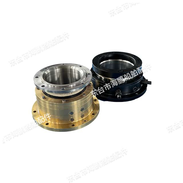
Marine seals do not operate in a vacuum. The physical characteristics of the water they operate in and the internal pressure dynamics of the vessel's cooling systems play a massive role in post-installation survival. A perfectly installed seal will fail rapidly if it is mismatched to its operating environment or starved of its required cooling flow.
Vessels operating in shallow rivers, high-silt estuaries, or coastal zones subject to heavy dredging face unique sealing challenges. Standard elastomeric lip seals and basic carbon graphite faces are highly susceptible to abrasive wear. Suspended sand and silt act as a continuous grinding paste against the seal interfaces. When standard components are deployed in these harsh environments, abrasive particles embed themselves into the softer materials. They rapidly wear down the opposing rotating surfaces.
Engineering specifications must match the operational profile. Installing an anti sand stern shaft seal is an operational necessity for vessels in particulate-heavy waters. These specialized devices incorporate hardened silicon carbide faces, multiple barrier chambers, and active flush systems. They purge abrasive grit away from the primary sealing lips before it causes mechanical damage.
Modern dripless seals rely on a continuous supply of injected water to provide cooling, lubrication, and positive pressure within the stern tube. This water injection line routes from the engine's raw water cooling circuit directly to the seal housing. The flow of water ensures that the internal pressure of the stern tube exceeds the external hydrostatic pressure of the ocean. This keeps the seal faces lubricated and prevents debris from migrating inward.
Post-installation failures frequently occur when this cooling circuit is compromised. Airlocks trapped in the injection line during the launch process starve the seal of water. Physical blockages from marine growth do the same. Without this critical flow, the system suffers a hydrodynamic imbalance. The seal runs dry, generating extreme friction that melts elastomeric bellows and shatters carbon stators within minutes of engaging the transmission.
To prevent hydrodynamic imbalance, verify the following cooling system parameters before launch:
Confirm the raw water injection line is routed with a continuous downward slope to prevent air trapping.
Verify the cross-over vent line is open and unobstructed on twin-engine installations.
Check the water flow rate at the seal housing injection port against the manufacturer's minimum gallon-per-minute requirement.
Ensure the raw water pickup grate is clear of marine growth and launch debris.
When post-installation leakage occurs, the engineering team must rapidly assess whether the situation can be stabilized while the vessel remains in the water. Sometimes an emergency haul-out is required. Making the wrong decision escalates a minor adjustment into a catastrophic flooding event. A structured diagnostic framework is essential for evaluating the appropriate corrective actions.
Certain interventions are safe to perform afloat, provided the crew understands the mechanical limits of the hardware. Other repairs physically require the removal of the propeller shaft, which mandates a dry dock environment.
Observed Issue | Physical Symptoms | On-Water Action (Afloat) | Dry Dock Action (Hauled Out) |
|---|---|---|---|
Under-compressed mechanical seal | Steady leak while stationary; bellows appears elongated. | Loosen set screws slightly, compress rotor to OEM spec, and retighten. | Inspect shaft for set screw burrs prior to resetting compression. |
Airlock in cooling line | Seal runs hot; squealing noise; steam venting. | "Burp" the seal by gently compressing the bellows to release trapped air. | Verify cooling line routing and ensure proper downward slope. |
Scored or corroded propeller shaft | Continuous heavy spray under load; lip seal cannot seat. | None. Bilge pumps must manage ingress until haul-out. | Remove shaft for machining, install a speed sleeve, or replace shaft. |
Contaminated mating faces | Consistent drip despite correct compression. | Flush faces with clean water; carefully wipe with lint-free material. | Disassemble seal, polish faces, and reassemble in a clean environment. |
If diagnostics reveal that the seal components are physically damaged, replacement is the only option. You might find a cracked carbon stator, a torn bellows, or a degraded lip seal. The marine environment is unforgiving. Utilizing substandard aftermarket components introduces severe operational risks. Engineering teams must prioritize sourcing OEM-verified replacement stern shaft seal parts to guarantee material compatibility and dimensional accuracy.
Evaluating replacement parts requires a strict assessment of material composition. For high-load commercial applications, upgrading from standard carbon graphite to silicon carbide faces provides superior resistance to thermal shock and abrasive wear. Selecting Viton elastomers over standard Nitrile rubber ensures better longevity in high-temperature, oil-rich environments. Replacement components for commercial vessels must carry appropriate classification society approvals, such as ABS, DNV, or Lloyd's Register. This maintains the vessel's operational compliance and insurance validity.
A failure event presents an opportunity to upgrade the vessel's sealing infrastructure. If a traditional stuffing box repeatedly causes shaft scoring and requires constant adjustment, upgrading to a dripless mechanical face seal or an advanced lip seal cartridge offers a massive operational advantage. These advanced systems eliminate the need for routine repacking. They protect the shaft from localized wear and maintain a completely dry bilge. This reduces the ambient humidity that accelerates corrosion on surrounding engine components.
Preventing post-installation leakage begins long before the vessel touches the water. Rigorous quality assurance protocols during the procurement and assembly phases drastically reduce the probability of premature failure. A proactive approach focuses on verifying hardware tolerances and utilizing expert oversight during the critical installation window.
Implementing strict marine sealing equipment quality control requires a comprehensive pre-installation checklist. Before any new seal is mounted, technicians must verify the condition of the vessel's existing hardware. This includes measuring the propeller shaft with a dial indicator to ensure runout falls within acceptable tolerances, typically less than 0.003 inches. The shaft surface must be meticulously inspected for pitting, grooves, and galvanic corrosion. Any imperfections in the sealing area must be addressed via machining or the installation of a stainless steel wear sleeve.
The new seal components must be inspected straight out of the box. O-rings should be checked for elasticity and absence of dry rot. Mechanical faces must be visually inspected under bright light to ensure no micro-fractures or factory contamination exists. The stern tube itself must be cleaned of old sealant, marine growth, and abrasive debris to ensure a secure, watertight fit for the articulating hose or primary housing.
The complexity of modern sealing systems often exceeds the scope of general shipyard labor. Improper DIY installations risk immediate mechanical failure and routinely void manufacturer warranties. To mitigate these implementation risks, operators should leverage certified technical oversight. Utilizing marine shaft seal installation support ensures that critical metrics are verified against factory specifications before the vessel is launched. Technicians confirm compression ratios, set-screw torque values, and cooling line routing.
Professional support provides a crucial layer of accountability. If an issue arises during the sea trial, having a certified technician on record simplifies warranty claims and accelerates the troubleshooting process. The initial investment in expert installation oversight pays dividends by preventing the catastrophic costs associated with emergency dry-docking and delayed operational schedules.
Once a seal is successfully installed and broken in, its long-term reliability depends entirely on a structured, ongoing maintenance program. Neglecting routine checks allows minor operational shifts to compound into major mechanical failures. A robust stern shaft seal maintenance framework focuses on preventative monitoring and system verification.
A preventative maintenance calendar dictates daily, weekly, and monthly inspection tasks. Daily engine room rounds must include a visual inspection of the seal housing to verify the absence of water or oil leaks. Technicians use an infrared thermometer to monitor the operating temperature of the seal stator. Sudden temperature spikes indicate a loss of cooling water or an increase in friction. Monthly checks focus on verifying the torque on all stainless steel hose clamps securing the articulating hose to the stern tube. Heavy engine vibration causes these clamps to back off over time.
The lifeblood of any modern seal is its cooling and lubrication system. Maintenance routines must ensure that raw water injection lines remain free of marine growth, scale buildup, and physical kinks. For twin-engine configurations utilizing a cross-over venting line, crews must verify that the valves remain open and the lines are clear. This prevents airlocks when operating on a single engine.
In commercial oil-lubricated systems, daily verification of the gravity header tank level is mandatory. Any sudden drop in oil level indicates an outboard seal breach. The presence of emulsified, milky oil indicates water ingress. Routine oil sampling and analysis help detect microscopic bearing wear and seal degradation long before a catastrophic physical failure occurs.
Download the OEM troubleshooting checklist to standardize your daily engine room inspections and catch thermal spikes early.
Measure your propeller shaft runout with a dial indicator to confirm it sits within the 0.003-inch tolerance before ordering new sealing components.
Contact a technical sales engineer to schedule remote diagnostic support for your current water ingress issues.
Audit your current spare parts inventory and replace any unverified aftermarket elastomers with certified OEM components.
A: Severe water ingress immediately after launch indicates a gross installation error. The most common causes are an under-compressed bellows failing to hold the mechanical faces together, a torn elastomeric lip seal, or a forgotten set screw allowing the rotor to slide forward. Immediate haul-out or emergency in-water adjustment is required to prevent flooding.
A: A dripless seal leaking at rest suffers from insufficient bellows compression or contamination between the mating faces. If the stainless rotor is not pushed far enough aft during installation, the hydrostatic pressure of the water forces the faces apart. Grit or grease left on the carbon face also prevents a watertight seal.
A: During the initial break-in period, a newly repacked stuffing box should drip approximately eight to ten drops per minute while the shaft is rotating. This water cools and lubricates the flax packing. When the shaft is stationary, the dripping should slow significantly or stop entirely.
A: Yes. Lip seals require a perfectly smooth, uniform shaft surface to maintain a watertight barrier. Microscopic scratches, grooves from old packing, or pitting from galvanic corrosion create channels that allow high-pressure water to bypass the new rubber lip instantly.
A: These specialized seals are designed for vessels operating in abrasive, shallow, or high-silt environments. They utilize hardened materials like silicon carbide and active flushing mechanisms to prevent suspended sand and grit from grinding away the primary sealing faces. This drastically extends the lifespan of the component.
A: An over-compressed seal generates excessive heat rapidly once the shaft begins turning. You will hear a high-pitched squealing noise, see steam venting from the housing, or measure abnormally high temperatures on the carbon stator. The bellows will appear tightly pancaked rather than appropriately tensioned.
A: Post-refit oil leakage results from damaging the delicate lip seals during shaft insertion, installing the seals facing the wrong direction, or failing to machine a worn shaft liner. Any oil leaking out means water can leak in. This requires immediate dry-docking to prevent catastrophic bearing failure.


